1. PROBLEM DESCRIPTION
Deacon Engineers carried out the design of large, rotating digesters for the treatment of municipal solid waste. The digesters are approximately 65m long and 4.5m in diameter and rotate continuously, at 1 rpm, while processing up to 500 tonnes of waste. Due to the cyclic nature of the loading, careful attention had to be paid to the fatigue design of the digesters. The standard adopted was British Standard 7608:1993 Code of practice for fatigue design and assessment of steel structures (BS 7608).

2. FATIGUE LOADING
BS 7608, along with other international standards for stress-life calculations of steel structures, are based primarily on the results of uniaxial fatigue test data. While the design approaches presented in the standards may be adequate for general structures, specialized mechanical equipment is often subjected to loads that generate a multi-axial, out of phase stress response. Neglecting the effect that cyclic, multi-axial stresses have on life predictions can lead to unsafe fatigue designs. Deacon Engineers use fe-safe™ software which can calculate critical plane fatigue lives, taking into account both the multi-axial stress response and the fact that applied loads often act out of phase to one another. This was the case in the tyre regions of the digester where global bending and local trunnion roller loads create multi-axial stress distributions.
3. CALCULATED FATIGUE LIVES
Resolving stresses onto planes in order to determine the plane with the most damage is critical in cases where multi-axial stresses are present. For a particular design detail, the following demonstrates how fatigue lives vary with the method that is used to calculate them. Consider the following multi-axial load history:
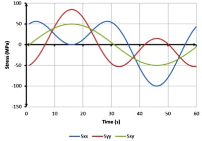
Using the techniques of BS 7608 and selecting the maximum principal stress range on planes that are not more than 45° apart produces a maximum range of 156 MPa. In this case the variation does exceed 45° making the process not only difficult and tedious but also non-conservative. When the critical plane method is employed, the maximum stress range increases by almost 20% to 186MPa. For a detail classified in accordance with BS 7608 as an F class detail, this results in a fatigue life reduction of around 40%.
4. DESIGN OUTCOME
Deacon Engineers adhered both to international fatigue design standards and to the latest fatigue life calculation techniques in order to account for the complex stress-time histories that the digesters were subjected to. Applying the standards alone, and ignoring out-of-phase and multi-axial loading, could have resulted in an unsafe design. The choice of digester design features, weld details and material thickness is a direct result of the fatigue life predictions. This highlights the need for accuracy and confidence in calculated results, without introducing conservatism that increases construction costs and adds weight to rotating equipment.
5. OTHER APPLICATIONS
The following are examples of rotating equipment which is subjected to multi-axial and out of phase loading:
- Kilns
- Mills
- Scrubbers
- Granulators
- Vehicle axles
- Drive shafts